2016 UPDATE:
This project has had a major upgrade to become DrillconUSB featuring new
electronics, mechanical improvements and new graphical host
software.
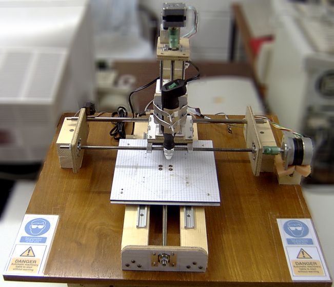
The worst bit of doing electronic projects for me is the drilling of all the holes in the PCB. Even with just a few chips, I'm soon running into hundreds of holes. I have a drill stand and miniature electric drill which helps but still it's a long and boring process. Most projects can't justify the cost of having a board made professionally either.
A little while ago, my old trusty Epson Stylus Color (sic) decided to block up its black printhead. I tried unblocking it with special cleaning fluid but some nozzles remained resolutely gummed up or even damaged. Since it was so old and the printheads were fixed, repairing it really wasn't an option. Time to throw it away and buy a new one. I couldn't just junk it without stripping it of useful parts though. I had seen other web sites where people had built their own CNC drilling machines (Computer Numerical Control) and an old printer contains stepper motors and precisely machined stainless steel rods. The Stylus Color was no exception. I salvaged two unipolar stepper motors, the main circuit board, the button panel and the carriage together with the printhead assembly.
I had never used stepper motors before so I did some research into how to control them. The unipolar ones are easy. You just need four output lines and a set of line drivers. So that was four output lines for each of the X, Y and Z axes plus an extra one to control the miniature drill power supply. Ideally I wanted some feedback sensors too so I would need at least one input line for each of the axes. Now it just so happens that I had a computer I/O board in stock thanks to a wonderful parcel of assorted components from my friend Aaron in Texas (now Tucson) - the National Instruments PC-DIO-24. Sure it's an old ISA bus card but it could be configured to provide sixteen lines of output and eight lines of input and there was a driver for Linux.
So here are the initial designs:
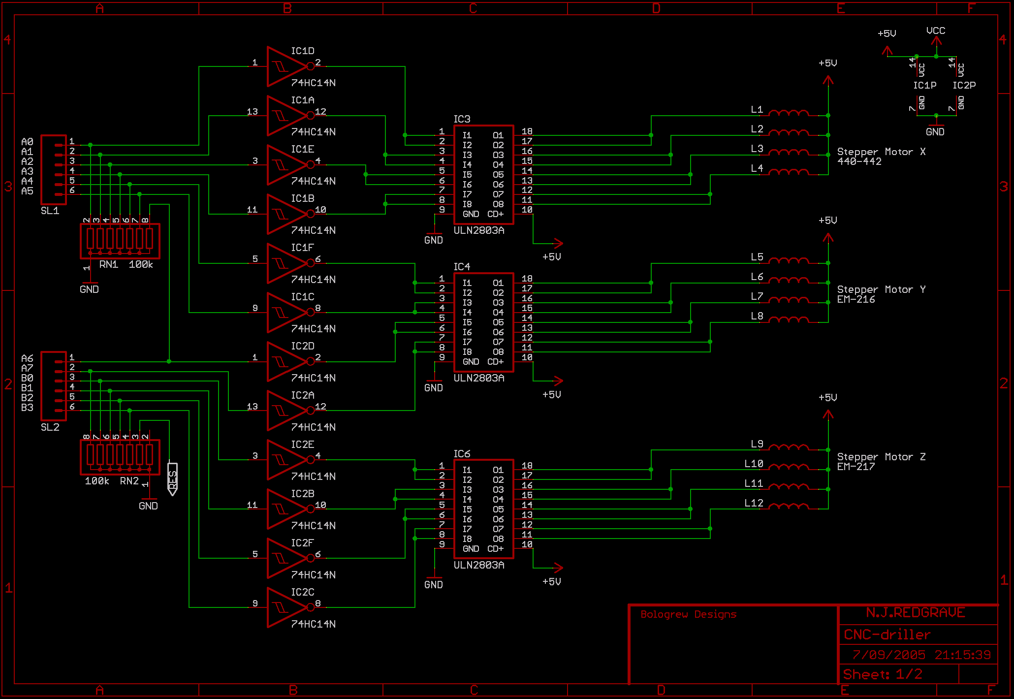
They are shrunk down but if you save the images you will get all the detail.
The first page handles the three stepper motors. The resistor arrays are there to pull down the CMOS inputs to prevent them from floating. The 74HC14N is an inverting buffer with Schmitt trigger inputs that clean up the signals from the I/O card. The ULN2803A is an inverting open collector Darlington line driver. The inversion undoes the inversion done by the 74HC14N. The inputs and outputs are doubled up to provide a maximum of 1A per motor coil. Theoretically, only two motor coils should be energised at any one time giving a total load of 2A per chip. The ULN2803A chips are therefore fitted with heatsinks.
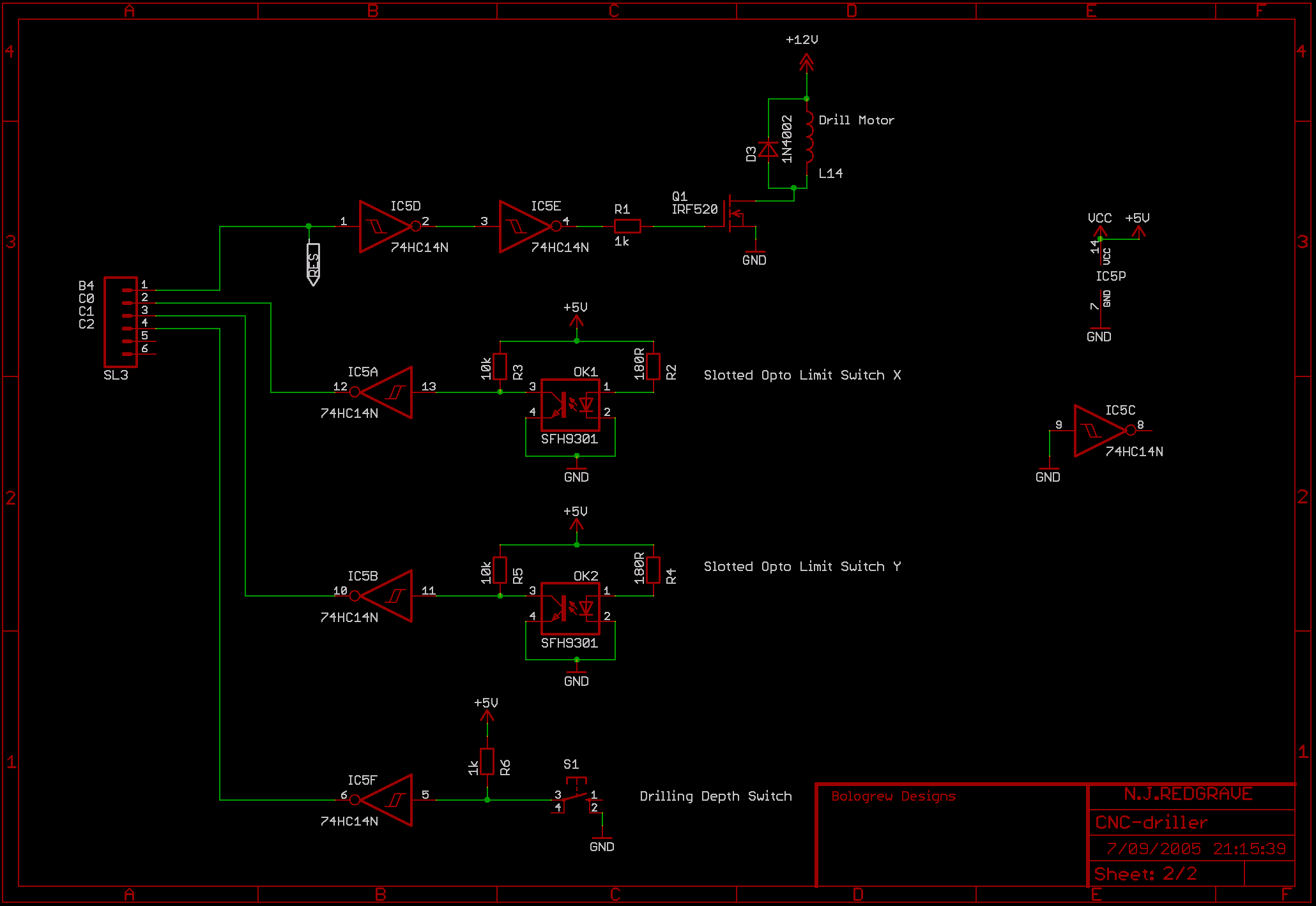
The second page handles the miniature drill motor control and the three input sensors. The drill motor control passes through two gates of a 74HC14N which cleans up the signal and undoes the inversion. That signal then connects to the gate of the IRF520 - an N-channel Power MOS transistor. It can handle a load of 10A with 100V which is a bit of an overkill but I had it in stock. The diode across the miniature drill coil prevents the back EMF from damaging the transistor.
That brings us to the input sensors. The sensors for the X and Y axes are slotted opto switches that I salvaged from a broken video recorder. All they are is an LED separated by a gap from a photo-transistor. Normally the infra-red light from the LED falls on the transistor and makes it conduct pulling the output low but when the beam is interrupted, the transistor stops conducting and the output goes high. This output is fed into a gate of a 74HC14N which cleans it up and inverts it. Lastly, the sensor for the Z axis drill depth is simply a sub-miniature push button switch salvaged from the Stylus Color button panel. The signal is high until the button is pressed pulling it low. As before, the output is cleaned up and inverted by the 74HC14N.
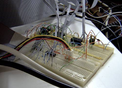
It's not pretty but it works - here is a picture of the circuitry wired up on a couple of breadboards:
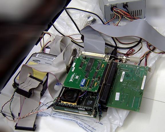
Here is a picture of the lash-up showing the PC-DIO-24 on top of the CPU board and the Ethernet card to the right:
I tried a few Linux distributions on this system but ended up using Damn Small Linux. It's a live CD-style distribution but it can be installed onto a hard disk. It's not the world's fastest machine but it still has enough power to run the X Window System. It is also configured to do NFS file sharing and can be remotely accessed/controlled with SSH. It's currently running the 2.4.29 kernel. Control of the PC-DIO-24 is thanks to the Comedi drivers. I discovered that this PC-DIO-24 had been a bit too "pre-enjoyed" and three of the I/O lines had been fried. There were sufficient alternate lines to work around that but I decided to replace the 82C55 which wasn't terribly expensive. There is no protection on the 82C55's I/O lines so the use of a buffer in my schematic was a good precaution.
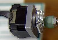
What little information I could find seemed to indicate that this was a 3.6 degree per step motor with a resistance of 11 Ohms per coil.
I found a little more information about the printhead motor that I decided to use for the Z axis:
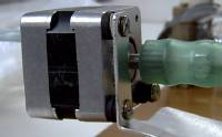
This one has a step size of 1.8 degrees, a coil resistance of 10 Ohms, a supply voltage of 3.0 to 10.0 Volts, a current per phase of 0.4 to 1.2 Amps and a continuous holding torque of 14.8 Ncm.
I did have a couple more stepper motors in stock that I salvaged from old DEC 8" floppy drives but my tests showed them to be rather weak, particularly considering that they would have to move the X axis which would also have the Z axis mounted on top. Since I had no experience with stepper motors and little real torque information on the current motors, I decided to wait until later to figure out what motor I would need for the X axis.
Time to think about the mechanical design...
The worst bit of doing electronic projects for me is the drilling of all the holes in the PCB. Even with just a few chips, I'm soon running into hundreds of holes. I have a drill stand and miniature electric drill which helps but still it's a long and boring process. Most projects can't justify the cost of having a board made professionally either.
A little while ago, my old trusty Epson Stylus Color (sic) decided to block up its black printhead. I tried unblocking it with special cleaning fluid but some nozzles remained resolutely gummed up or even damaged. Since it was so old and the printheads were fixed, repairing it really wasn't an option. Time to throw it away and buy a new one. I couldn't just junk it without stripping it of useful parts though. I had seen other web sites where people had built their own CNC drilling machines (Computer Numerical Control) and an old printer contains stepper motors and precisely machined stainless steel rods. The Stylus Color was no exception. I salvaged two unipolar stepper motors, the main circuit board, the button panel and the carriage together with the printhead assembly.
I had never used stepper motors before so I did some research into how to control them. The unipolar ones are easy. You just need four output lines and a set of line drivers. So that was four output lines for each of the X, Y and Z axes plus an extra one to control the miniature drill power supply. Ideally I wanted some feedback sensors too so I would need at least one input line for each of the axes. Now it just so happens that I had a computer I/O board in stock thanks to a wonderful parcel of assorted components from my friend Aaron in Texas (now Tucson) - the National Instruments PC-DIO-24. Sure it's an old ISA bus card but it could be configured to provide sixteen lines of output and eight lines of input and there was a driver for Linux.
The Circuit Design
It was time to design the electronics and test the existing hardware.So here are the initial designs:
They are shrunk down but if you save the images you will get all the detail.
The first page handles the three stepper motors. The resistor arrays are there to pull down the CMOS inputs to prevent them from floating. The 74HC14N is an inverting buffer with Schmitt trigger inputs that clean up the signals from the I/O card. The ULN2803A is an inverting open collector Darlington line driver. The inversion undoes the inversion done by the 74HC14N. The inputs and outputs are doubled up to provide a maximum of 1A per motor coil. Theoretically, only two motor coils should be energised at any one time giving a total load of 2A per chip. The ULN2803A chips are therefore fitted with heatsinks.
The second page handles the miniature drill motor control and the three input sensors. The drill motor control passes through two gates of a 74HC14N which cleans up the signal and undoes the inversion. That signal then connects to the gate of the IRF520 - an N-channel Power MOS transistor. It can handle a load of 10A with 100V which is a bit of an overkill but I had it in stock. The diode across the miniature drill coil prevents the back EMF from damaging the transistor.
That brings us to the input sensors. The sensors for the X and Y axes are slotted opto switches that I salvaged from a broken video recorder. All they are is an LED separated by a gap from a photo-transistor. Normally the infra-red light from the LED falls on the transistor and makes it conduct pulling the output low but when the beam is interrupted, the transistor stops conducting and the output goes high. This output is fed into a gate of a 74HC14N which cleans it up and inverts it. Lastly, the sensor for the Z axis drill depth is simply a sub-miniature push button switch salvaged from the Stylus Color button panel. The signal is high until the button is pressed pulling it low. As before, the output is cleaned up and inverted by the 74HC14N.
It's not pretty but it works - here is a picture of the circuitry wired up on a couple of breadboards:
The Computer
The computer powering this contraption was given to me by my ex-boss. It's a powerhouse - a 100MHz 486 with 64MB of memory. It does have onboard graphics though. So it's basically an embedded CPU board with an ISA connector that can be plugged into a passive bus. The passive bus in this case coming from an old Viglen Genie which were very neat desktop machines. For software installation, I hooked up a floppy drive and a CDROM drive to this board but they weren't going to be there in the final design. I also added an SMC-Ultra Ethernet card.Here is a picture of the lash-up showing the PC-DIO-24 on top of the CPU board and the Ethernet card to the right:
I tried a few Linux distributions on this system but ended up using Damn Small Linux. It's a live CD-style distribution but it can be installed onto a hard disk. It's not the world's fastest machine but it still has enough power to run the X Window System. It is also configured to do NFS file sharing and can be remotely accessed/controlled with SSH. It's currently running the 2.4.29 kernel. Control of the PC-DIO-24 is thanks to the Comedi drivers. I discovered that this PC-DIO-24 had been a bit too "pre-enjoyed" and three of the I/O lines had been fried. There were sufficient alternate lines to work around that but I decided to replace the 82C55 which wasn't terribly expensive. There is no protection on the 82C55's I/O lines so the use of a buffer in my schematic was a good precaution.
The Motors
I wasn't able to dig up much information on the two motors from my Stylus Color. I decided to use the paper roller feed motor for the Y axis:What little information I could find seemed to indicate that this was a 3.6 degree per step motor with a resistance of 11 Ohms per coil.
I found a little more information about the printhead motor that I decided to use for the Z axis:
This one has a step size of 1.8 degrees, a coil resistance of 10 Ohms, a supply voltage of 3.0 to 10.0 Volts, a current per phase of 0.4 to 1.2 Amps and a continuous holding torque of 14.8 Ncm.
I did have a couple more stepper motors in stock that I salvaged from old DEC 8" floppy drives but my tests showed them to be rather weak, particularly considering that they would have to move the X axis which would also have the Z axis mounted on top. Since I had no experience with stepper motors and little real torque information on the current motors, I decided to wait until later to figure out what motor I would need for the X axis.
Time to think about the mechanical design...