I had a chipboard with wood veneer sheet that would do for the baseboard. I had well-seasoned marine ply that would make good mounting brackets and I had soft pine batten for miscellaneous mounting duties.
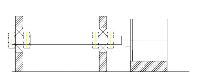
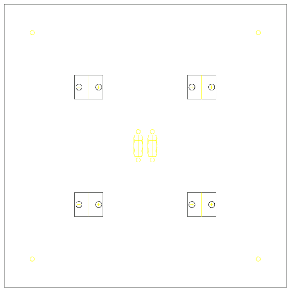
I could cut a square steel plate for the Y axis moveable bed from the case of the afore-mentioned Viglen Genie. I wanted it to be 20.0 by 20.0 cm because that would give the drill a reach of 10.0 cm on either side of the midpoint. Then the question of how to support this plate arose. I looked at smooth sliding rods but I couldn't come up with something cheap enough or something I thought I could get to work. Then I found the "DryLin N Low Profile Linear Guide" on the RS Components web site. The bottom of the range version is a 30.0 cm long aluminium rail with mounting holes. Into this rail are inserted 2.0 cm long carriages onto which can be mounted things like plates. So I decided on two rails and four carriages. This was the most expensive piece of the project at the time but I thought it would give me maximum chance of success. The parallel rails would not only keep the plate in line but would also prevent any movement in the Z axis. With two carriages inserted into each rail, the plate should essentially be self-aligning. The other advantage of the DryLin system is in its name - they don't require any lubrication. The problem with lubricating surfaces in a project like this is that drill shavings stick to the lubricant if it's something like oil.
Here's a picture of the plate with the mounting positions of the four carriages, the four holes to mount a wooden plate on top of the steel one and the mounting position of the central nuts which would attach the plate to the threaded rod:
Now the question arose of how I was going to accurately make all the parts to sufficent tolerances that would allow this machine to function. If I had a drilling machine, I wouldn't need to build this in the first place. Then I realised that I did have a high precision piece of equipment that would do the job - my new Canon PIXMA iP1000 printer that I bought to replace my Stylus Color. The QCad program could print the designs with 1:1 scaling and all I had to do was cut them out and glue them to the pieces I was trying to measure and cut. The external shape of most of the pieces wouldn't be that crucial - it was the relative positions of the internal mounting points that really mattered.
I had a plan. If the Y axis didn't work then there would be no point in trying to build the Z or X axes. I ordered the DryLin Linear Guides from RS Components and the remainder of the electronic and mechanical parts from Farnell. Normally I would use Maplin but I could only get certain components from Farnell and they have a minimum order amount of £20 which I couldn't otherwise meet.
Time to start construction...