Then the computer died and I had to put into action the designs I have been working on from time to time.
The new plan was to turn Drillcon into a USB peripheral and give it the ability to perform simple actions that could be chained together to make a drilling machine. The task of translating the drilling coordinates into the primitives that the USB subsystem could understand would then be handled by the host and its software which I planned to make cross-platform for maximum flexibility.
The new controller subsystem consists of a USB to Serial converter connected to a PIC micro-controller capable of running five million instructions per second. This allowed me to implement a soft serial port running at 115,200 bps and all communication to and from the subsystem is check-summed for safety. The control loop is timer based but polled rather than interrupt driven. This was done to ensure the serial communication always worked. This means that the control loop to change the stepper motor drive patterns can slow down but can not speed up and exceed the clock rate. A practical speed limit of approximately 43,000 steps per second has been measured. This far exceeds the rate at which my stepper motors can be run but the extra speed has come in useful. Not only can the subsystem use full steps or half steps but each axis also has a 6 bit stepdown which effectively means that the drill can move in the XY plane at roughly 2500 different angles per quadrant. In other words, it can perform linear routing in the subsystem without any further assistance. The stepdowns can massively slow the stepper motors down but some of that slowdown can sometimes be compensated for by the much higher possible clock rate. It should be noted that the system understands two speeds - maximum stepper motor speed and routing/drilling speed. The maximum stepper motor speed is set purely by the stepper motors used and the loading on them. The routing/drilling speed is set accordingly to the material the machine is drilling or routing through. The system also switches between half steps and full steps to get both the highest precision and maximum seek speed.
The new host software is written in C++ using the Qt toolkit and the Qt Creator IDE. I'm writing it using a Linux PC but with Qt being cross-platform, it should be possible to rebuild it for Mac and Windows PCs and possibly even Android tablets. As before, it takes a simplified Excellon drilling format and can handle drilling and routing. In fact, it has three routing modes: full routing, drawing mode (no drill power required), and laser stencil mode (no plunging and retracting required). At long last I'll be able to properly test my laser cutter and see if it's able to cut PCB stencils.
I haven't yet completed the full functionality of the software but already most functions are available (some manual commands are not yet enabled). The host software is under the GPL licence. The software should build with Qt4 or Qt5 but if you are using Qt4 then you first have to build and install the Qt SerialPort software. Qt5 has it already built-in.
The Circuit Design
Here are the new designs. The Serial to USB converter is based on the FT8U232AM chip by FTDI. I used it because I had one left in stock. If I was designing the circuitry right now, I would use the FT232R chip by FTDI and integrate it directly onto the PIC board.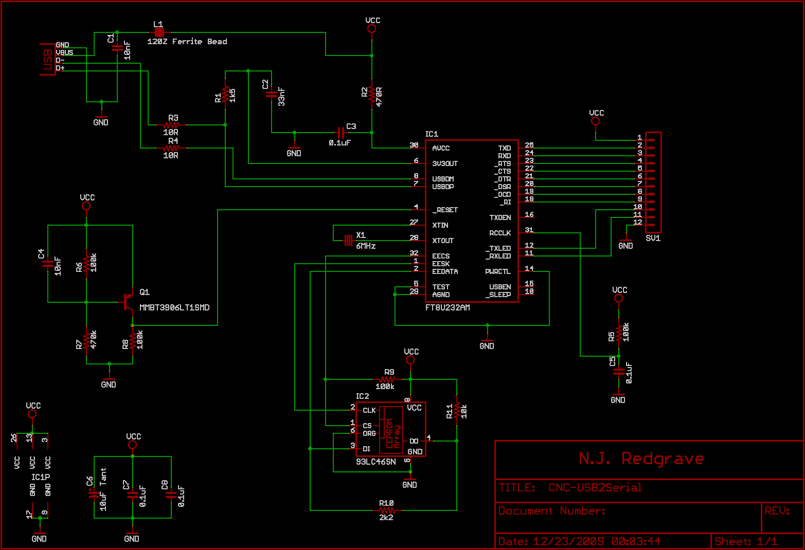
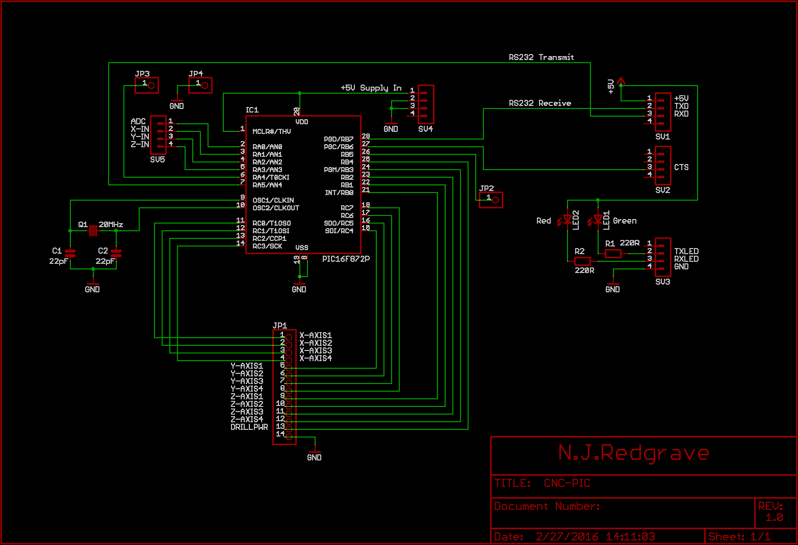
This is the PIC board. All unused I/O lines are brought out to headers just in case they are needed in future. One I/O line happened to be for an ADC so not only is that line brought out to a header but the software has provision to start a conversion and read the result. The LEDs on this board are actually used to display the serial data transmitted and received by the USB to Serial board.
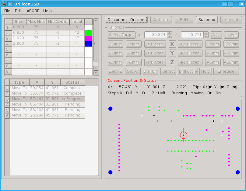
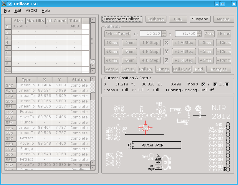
The Host Software
Here are pictures of the software in drill and route modes:
Update
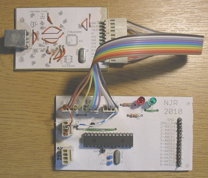
Here are the Serial to USB and PIC micro-controller boards fitted into the base of the drilling machine and wired up to the existing drive board which now has a fan to cool the driver chips: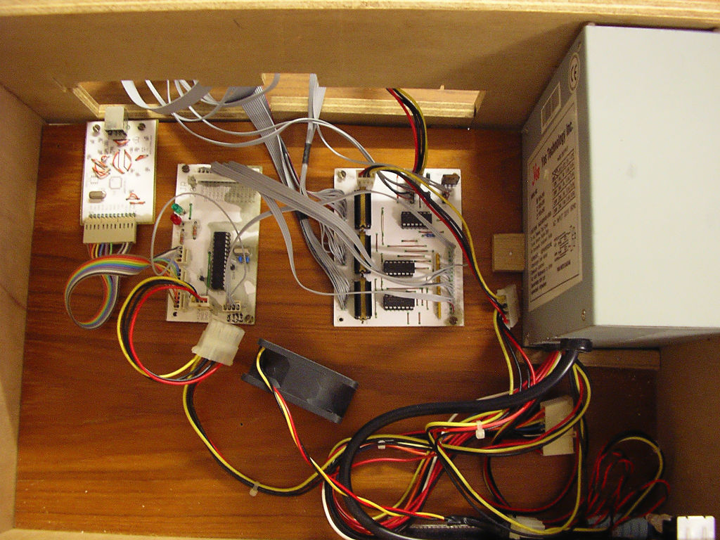
The Z axis sensor unit produced an inverted signal compared to the X and Y axis sensors so I used the spare inverter gate on the drive board to invert it again. This simplifies the code in the micro-controller when the "suspend when sensor activated" function is used. It doesn't matter which way round the sensors are as long as all three are the same way round. However, they do have to match the code in the micro-controller and there are two lines that have to be commented/uncommented depending on which way round they are. This functionality is currently unused in the host software but the current state of the sensors is displayed in the "Trips" section.
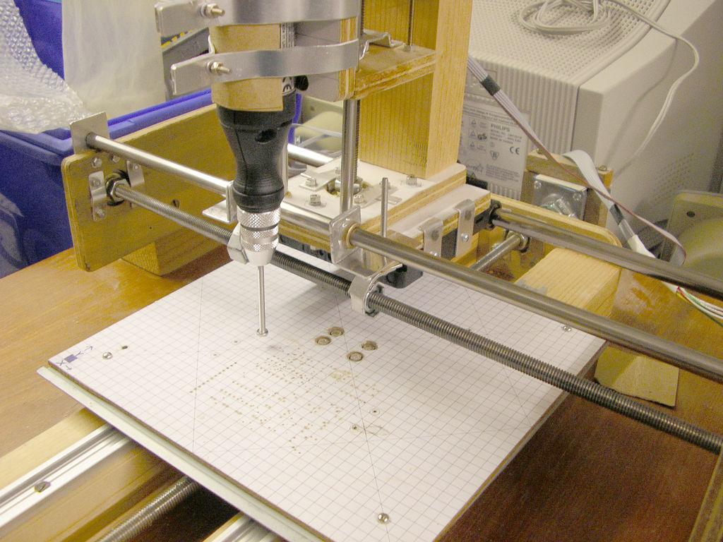
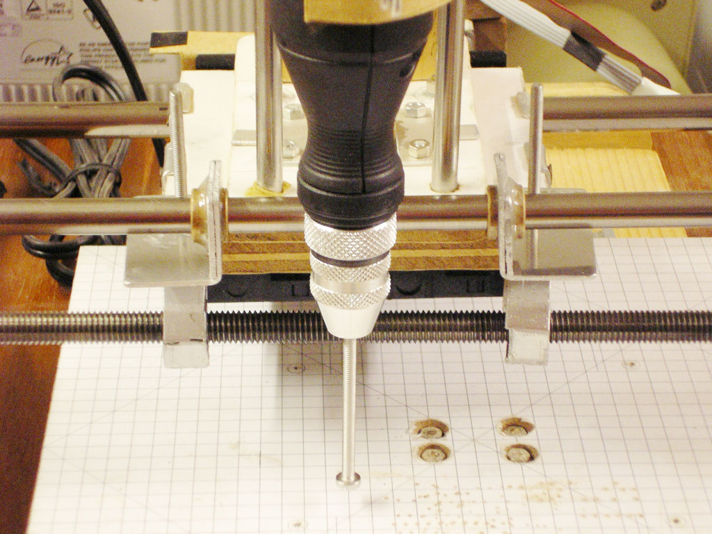
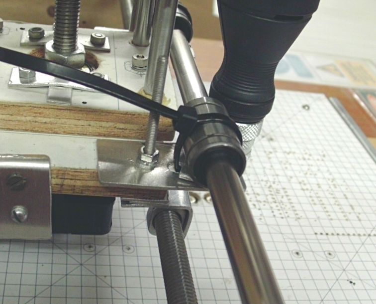
I have also upgraded the mechanism of the machine itself. When I first built it I used the threaded bar as a support as well as the rotary to linear motion converter. This was a mistake as the bar was not really rigid enough. However, as long as I was just doing drilling it did work sufficiently well. I am now attempting to make the machine operate as a milling machine too and for that, a much more rigid X axis is essential. I have fashioned a couple of brackets and fitted bushes into them to act as bearings with the new support bar. They're not as good as real bearings but they didn't cost me anything. I'll splash out on proper bearings when I build the next machine incorporating all my knowledge of what not to do again. The threaded bar really needs to be moved to a new location but building brackets to hold the nuts is currently too difficult. I'm hoping that if I can get this machine to work as a milling machine then I will be able to machine some new brackets either out of aluminium if it's up to the task or out of HDPE plastic of which I can make blocks by melting down milk containers. I also have to write a new host control program to translate G code into the control board's protocol - I'm thinking "MillconUSB".
Update 2
Well those bushings didn't work well. They had too
much friction so I had to fit proper linear bearings after
all. The new bearings are only cable tied on but
that seems to work pretty well. While I was at it, I
took the opportunity to finally replace those horrid
nutblocks. Hopefully I won't have to get this
machine to do milling after all. I have a whole new
machine in the design pipeline...
Resources
PIC source code: DrillconPIC.zip
DrillconUSB host C++/Qt software: DrillconUSB_PC.zip
Qt Serialport for Qt4: qtserialport.zip
Eagle drilling script: Eagle-drill_CAM.txt
Eagle routing script: Excellon-route.ulp
Compiled version of DrillconUSB (32bit Qt4): drillconusb-snapshot.tar.gz