The Z Axis Construction


I now had a bit of a problem.  I had blown my budget on the DryLin linear guides on the Y axis.  Those same guides would make a very good Z axis but I couldn't really afford them.  However, from the same old DEC floppy drive that I mentioned earlier, I had also salvaged some stainless steel rods.  They would make good sliding guides.  I couldn't afford any linear bearings either but I had noticed that when I filed the marine ply, it became very smooth but still very hard.  Perhaps I could do without proper linear bearings?  So I came up with a design with two fixed end brackets containing bearings and two sliding plates joined together by a front plate.  The miniature drill would be bolted to the front plate using aluminium straps.

Here are the designs:
Z plates

Z front plate

As before, I could bolt the marine ply together to make two brackets for the price of one.  However, since the stainless steel rods had to pass through all four pieces of wood, both pairs of brackets had to be bolted together as well in order to get the alignment right.
Here are the brackets:
Z brackets

Time to fit the bearings, the stainless steel rods and see how it hangs together:
Z fit test

Now the batten backbone is attached and the frontplate for the inner brackets:
Z assembled

No matter how careful you are, once you attach the frontplate, it will twist the inner brackets and make it difficult to slide the mechanism.  At this point I coated the inside of the inner bracket holes with floor polish containing silicone to make them nice and slippery.

Now I fitted the bearings using a better method than that of the Y axis:
Z bearing1Z bearing2

To sort out the twisting of the inner brackets, I now fitted tensioning bars made out of 8BA threaded brass rod.  It turned out that I had to pull one side in and push the other side out the make it square again.  Once again, it slid freely along the rods.
In order to make the inner brackets move along the threaded rod, I needed to fit some captive nuts.  For the same reason as the Y axis, two were needed to avoid any backlash.  I made two brackets out of aluminium and trapped the nuts between them and the wooden bracket.

Here's the combined result:
Z tensioning and captive nuts

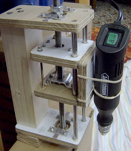
Moment of truth time.  I lashed my miniature drill to the frontplate and attached the second Stylus Color motor to the threaded rod which hadn't been cut to the right length yet:
Z lift test1Z lift test2

Yes, it had no problem raising and lowering the mechanism.  It was even slower than the Y axis though due to the higher resolution of the motor.
Now I replaced the regular nuts with lock-nuts, cut the threaded rod to the right length, fitted aluminium straps to the front plate for the drill mounting and made a bracket to hold the stepper motor above the threaded rod.  As before, I coupled the motor to the shaft with hosepipe.

So here is the finished Z axis:
Z finished

Phew!  Well let's press on with the final axis...