The Y Axis Construction

I designed an endplate to mount the bearings in with wooden battens between them on which would be mounted the linear guides.

Here's the endplate:

Y endplate
Now the problem was how to make two identical plates.  Simple - you don't.  You make one plate.  Having glued the paper design to the marine ply, I put another piece behind it and clamped it in a vice.  I drilled the holes for the bearing mounts and batten mounts and then screwed the two blocks together.

Here they are:
Y endplates
Now I could effectively treat the two plates as one.  I cut round them and then started the arduous task of first drilling out and then filing out the hole for the bearing.  I got better at making the holes for the bearings as I worked on the other axes.  Fortunately, the position of the bearing holes wasn't crucial for this axis because the precise positioning was going to be done by the linear guides.  Once the plate was complete, all I had to do was to unscrew it and I had a pair of plates.

Like this:
Y endplates

The next job was to cut out the steel plate with a jigsaw, glue the paper design to it and drill the mounting holes for the DryLin carriages, threaded rod mountings and the wooden plate mountings.  Then the carriages were slid into the guides and the plate screwed into the carriages.  At that point I could screw the two wooden battens to my baseboard and screw the guides onto the battens.

Like this:
Y plate mounted
It took a fair bit of tweaking to get the plate running freely.  Any slight misalignment tends to make it bind.  In the end though, I could push it along the guides easily while maintaining virtually no play in the X or Z axes.

Time to put the bearings in with regular nuts and see how it all fits together:
Y endplate testfit

Now I could measure the distance from the nuts to the bottom of the plate in order to design the mounting bracket.

Here's what I came up with:
Y plate mounting
The idea is to sandwich two nuts between a set of plates.  The plates are deliberately roughened so the nuts won't slip and the smaller insert plate has lips on either end to limit the travel of the nuts anyway.  I used two nuts rather than one to prevent backlash.  Backlash is where there is play between a nut and the threaded rod so that it is possible to reverse the direction of the rod rotation and no movement of the nut occurs until the play is taken up.  With two nuts, they can be arranged so that the play is taken out of the system.  This does increase friction though.

Here's the finished sandwich:
Y plate mounting
This is then bolted to the underside of the Y axis plate.

Now with the threaded rod fed through the sandwich, the end plates can be aligned and screwed to the battens.  The bearings are locked into position with thin aluminium plates:
Y endplate
The inner bearing plates weren't too pretty since the bearings are thinner than the marine ply they are mounted in.  I improved the mounting method for later axes:
Y inside bearing

The nuts at this stage were still regular ones.  Once I tightened them up, I found I couldn't turn the threaded rod easily.  I had enough misalignment to make the rod bind in the front bearing.  I realised that the threaded rod only had to held tightly in the rear bearing since the plate itself was fixed to sliding in the linear guides.  So I filed out the front bearing housing and allowed it much more freedom to move.  That loosened the mechanism up sufficently so that I could now easily turn the threaded rod.
With the mechanism almost complete, I replaced the regular nuts with lock-nuts - one either side of each bearing.  I also used spray polish containing silicone on the threaded rod to lubricate it.  The silicone makes it more slippery while being a dry lubricant that won't make dust and drill shavings stick to it too much.

Time to do some tests.  I connected the Y axis stepper motor to the threaded rod with a piece of plastic hosepipe.  It's strong enough to transmit the power while being flexible enough to allow some misalignment of the shafts.  I clamped my vernier ruler to the plate and used the test program to rotate the shaft 1000 steps at a time while I noted the distance moved.

Here's the setup:
Y precision
I should note at this point that the test program was written to generate half steps.  As the name suggests, this halves the angle of a normal step by periodically energising two motor coils so the shaft is balanced between two normal step positions.  So where I talk about steps, I'm usually talking about half steps.
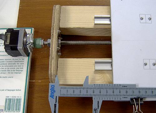
Anyway, after 16000 steps, the plate had moved 103.85 mm.  That's roughly 6.5 thousandths of a millimetre per step or 154 steps per millimetre!  Not too shabby at all.  It's not fast but it's better to be precise and accurate.

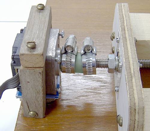
The final job was to build a mounting bracket for the stepper motor.  Although I used two Jubilee clips to connect the motor to the threaded rod, the one connecting the hose to the rod turned out to be superfluous.  The bracket isn't very pretty but it's easy enough to remove it should I need to fit a more powerful motor, say, for doing routing as well as drilling.  I'm not sure this motor is really powerful enough for routing but I haven't actually tried it yet.
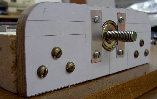
The mounted motor:
Mounted motor

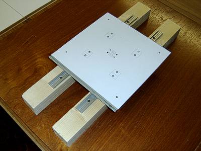
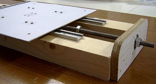
So here is the finished Y axis:
Finished Y axis

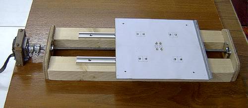
With this success under my belt, it was time to move on to the next axis - the Z axis.