I've been working on a project for a while
now
that has a lot of circuitry. Squeezing it into the
required space
has forced me to replace nearly all the leaded components with
their
surface mount counterparts.
Although complex, I still have the ability to manufacture the printed circuit board for this project. The problem is that I don't think I can successfully populate the board with all these components. Hand soldering a couple of surface mount chips is one thing - hand soldering dozens of surface mount components including some with a very fine pitch is another thing entirely.
So the project has sat neglected for a while.
Recently, my enthusiasm for the project was reawakened and I started looking for alternatives. Hot air rework equipment was far too expensive for my pocket but I came across a web site that was using an electric skillet to perform reflow soldering. Now there's an idea and better still, my mother has an old one she doesn't use anymore.
They were using solder paste and putting the components on top. They then placed the PCB in the electric skillet and turned up the heat. In due course, the solder paste melted and the components were firmly attached to the board. Even better, as the paste melted, the surface tension of the solder made the components automatically align with the pads if they were slightly off centre.
Now came the catch. To apply the solder paste to the PCB, they first had a solder mask or stencil made for them and then squeegeed the paste onto the board through the stencil. I looked into getting stencils made and the cost was horrifying - initial setup charges and cost per square centimeter.
So I had a think as to how I could make my own stencils. My first idea was to get thin copper sheets, lacquer one side and spray the other with photo-resist. Then I could use my UV lightbox and usual etching procedure. It sounded plausible until I tried to find a supplier of thin copper sheets. Even when I found something close, the cost was very high and my experience at making my own photo-sensitive boards has not been good.
So I looked again at how the stencils are made professionally. The ones for production runs are made out of stainless steel and the holes are cut out with a laser. The cheap stencils that the electric skillet web site people were using were made out of flexible plastic sheets but again cut by a laser. So I looked up A4 size laser stencilers. Well, if you've got several thousand pounds handy then you can rush out and buy one. Perhaps I could build my own though. I've already built a machine that can accurately position a drill bit in three dimensions and I already programmed it to do routing as well as drilling so all I needed to do is to replace the drill bit with a laser cutter.
Various Google searches later and I see people with souped up laser pointers lighting matches, cutting black tape and bursting balloons. Many people seemed to be using the laser out of a DVD burner for this task and the power output appeared to be around the 200 mW mark. I checked various component suppliers and found that Farnell stocked a 200 mW 808 nm laser diode. They also stocked a laser diode controller chip which monitors the photodiode embedded in the laser package that helps prevent any damage to the laser (which are very sensitive to spikes and the like) and which lets you control the output power with a single resistor. The laser diode was about £15 and the controller chip about £6 - cheap enough to give it a bash.
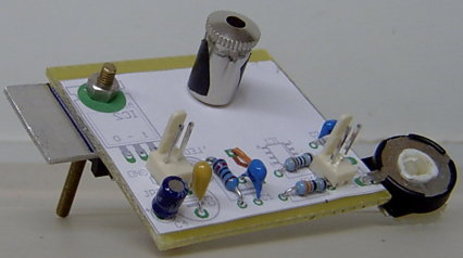
The large area of copper under the laser controller chip acts as a heatsink.
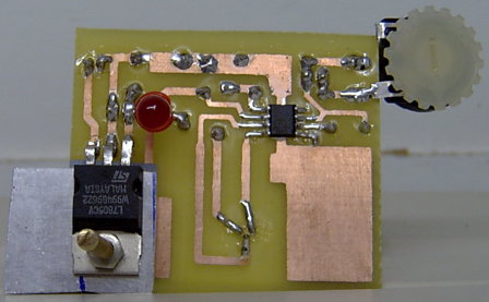
The top of the PCB can be seen at the top of the page and here is the track side:
If you know your physics then you might have spotted a flaw in this plan. The laser operates at 808 nm - that's in the infra-red. Just how do you work with something you can't see - especially when it is potentially dangerous? A domestic laser pointer is rated at about 1 mW. This device is rated at 200 mW. It'll burn your retinas and you won't even see it coming. The red LED is in the circuit specifically to warn me that the power is on.
Fortunately there is an easy solution. Digital cameras are sensitive to infra-red but usually have an infra-red cut filter to remove it. I have an old digital camera that I deliberately removed the IR cut filter from and covered the lens with blank 35 mm film that blocks visible light. The result is a digital camera that only sees in the infra-red and which helpfully has a composite video output that I can plug into a video monitor. I also have a monochrome video camera module that doesn't have an IR cut filter and so can see infra-red light too.
Initially the laser diode was completely bare. I didn't realise that laser diodes don't produce a tight beam of light. Instead they spray it out in a squashed cone. So it "looked" bright but was completely useless for my purposes. What you need is a collimating lens.
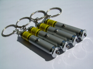
Now I've got a little keychain laser pointer and it was about to be sacrificed to science.
I had to ram the contents of the slim metal tube out and the laser, together with its circuitry, didn't survive the experience. However, the short inner metal tube was manufactured to take exactly the same size of laser diode as I was using. So I fitted it over the top of mine and attempted to produce a collimated beam by adjusting the spring-loaded lens under a threaded slug with a hole in it. It worked quite nicely but the lens was so small and so far away from the laser that a lot of the light was just bouncing around inside the can rather than hitting the lens. The other thing is that I didn't want a collimated beam - I want a beam focused to a point. If a collimating lens can take light from a point source and produce a parallel beam then another collimating lens reversed should take a parallel beam and focus it to a point.
I searched around and found some cheap acrylic collimating lenses at www.thorlabs.com. The first one, the CAY033, needed to be positioned very close to the laser window so it collected all the light. The second one, the CAX183, needed to have a much longer focal length so the light would be focused a couple of centimeters away.
I had to replace the spring in the can with a larger diameter one and make it quite short so the lens could get close to the laser window. I also had to drill out the threaded slug so that the hole could let the larger beam out.
Using a paper clip as a box spanner, I could then adjust the focus of the lens until I got a collimated beam.
The laser pointer also had a threaded top cap with a hole in it. I drilled that out and superglued the second collimating lens into it. Then I screwed that into the tube which had the added advantage of acting as a lock nut to the first collimating lens.
The picture at the top of the page shows the tube with the original optics. There is a small hole in the side of the metal tube which acted as a power light in the keychain pointer. I don't want invisible infra-red sneaking out the side so I stuck some black tape over it - I'm the first to admit it's not pretty.
Although complex, I still have the ability to manufacture the printed circuit board for this project. The problem is that I don't think I can successfully populate the board with all these components. Hand soldering a couple of surface mount chips is one thing - hand soldering dozens of surface mount components including some with a very fine pitch is another thing entirely.
So the project has sat neglected for a while.
Recently, my enthusiasm for the project was reawakened and I started looking for alternatives. Hot air rework equipment was far too expensive for my pocket but I came across a web site that was using an electric skillet to perform reflow soldering. Now there's an idea and better still, my mother has an old one she doesn't use anymore.
They were using solder paste and putting the components on top. They then placed the PCB in the electric skillet and turned up the heat. In due course, the solder paste melted and the components were firmly attached to the board. Even better, as the paste melted, the surface tension of the solder made the components automatically align with the pads if they were slightly off centre.
Now came the catch. To apply the solder paste to the PCB, they first had a solder mask or stencil made for them and then squeegeed the paste onto the board through the stencil. I looked into getting stencils made and the cost was horrifying - initial setup charges and cost per square centimeter.
So I had a think as to how I could make my own stencils. My first idea was to get thin copper sheets, lacquer one side and spray the other with photo-resist. Then I could use my UV lightbox and usual etching procedure. It sounded plausible until I tried to find a supplier of thin copper sheets. Even when I found something close, the cost was very high and my experience at making my own photo-sensitive boards has not been good.
So I looked again at how the stencils are made professionally. The ones for production runs are made out of stainless steel and the holes are cut out with a laser. The cheap stencils that the electric skillet web site people were using were made out of flexible plastic sheets but again cut by a laser. So I looked up A4 size laser stencilers. Well, if you've got several thousand pounds handy then you can rush out and buy one. Perhaps I could build my own though. I've already built a machine that can accurately position a drill bit in three dimensions and I already programmed it to do routing as well as drilling so all I needed to do is to replace the drill bit with a laser cutter.
Various Google searches later and I see people with souped up laser pointers lighting matches, cutting black tape and bursting balloons. Many people seemed to be using the laser out of a DVD burner for this task and the power output appeared to be around the 200 mW mark. I checked various component suppliers and found that Farnell stocked a 200 mW 808 nm laser diode. They also stocked a laser diode controller chip which monitors the photodiode embedded in the laser package that helps prevent any damage to the laser (which are very sensitive to spikes and the like) and which lets you control the output power with a single resistor. The laser diode was about £15 and the controller chip about £6 - cheap enough to give it a bash.
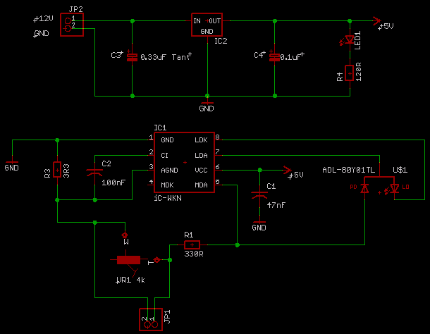
The Circuit Design
Using the datasheet from the laser controller chip, the design is pretty simple:Here is the board design:
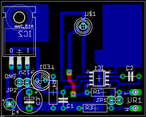
The large area of copper under the laser controller chip acts as a heatsink.
The top of the PCB can be seen at the top of the page and here is the track side:
If you know your physics then you might have spotted a flaw in this plan. The laser operates at 808 nm - that's in the infra-red. Just how do you work with something you can't see - especially when it is potentially dangerous? A domestic laser pointer is rated at about 1 mW. This device is rated at 200 mW. It'll burn your retinas and you won't even see it coming. The red LED is in the circuit specifically to warn me that the power is on.
Fortunately there is an easy solution. Digital cameras are sensitive to infra-red but usually have an infra-red cut filter to remove it. I have an old digital camera that I deliberately removed the IR cut filter from and covered the lens with blank 35 mm film that blocks visible light. The result is a digital camera that only sees in the infra-red and which helpfully has a composite video output that I can plug into a video monitor. I also have a monochrome video camera module that doesn't have an IR cut filter and so can see infra-red light too.
Initially the laser diode was completely bare. I didn't realise that laser diodes don't produce a tight beam of light. Instead they spray it out in a squashed cone. So it "looked" bright but was completely useless for my purposes. What you need is a collimating lens.
Now I've got a little keychain laser pointer and it was about to be sacrificed to science.
I had to ram the contents of the slim metal tube out and the laser, together with its circuitry, didn't survive the experience. However, the short inner metal tube was manufactured to take exactly the same size of laser diode as I was using. So I fitted it over the top of mine and attempted to produce a collimated beam by adjusting the spring-loaded lens under a threaded slug with a hole in it. It worked quite nicely but the lens was so small and so far away from the laser that a lot of the light was just bouncing around inside the can rather than hitting the lens. The other thing is that I didn't want a collimated beam - I want a beam focused to a point. If a collimating lens can take light from a point source and produce a parallel beam then another collimating lens reversed should take a parallel beam and focus it to a point.
I searched around and found some cheap acrylic collimating lenses at www.thorlabs.com. The first one, the CAY033, needed to be positioned very close to the laser window so it collected all the light. The second one, the CAX183, needed to have a much longer focal length so the light would be focused a couple of centimeters away.
I had to replace the spring in the can with a larger diameter one and make it quite short so the lens could get close to the laser window. I also had to drill out the threaded slug so that the hole could let the larger beam out.
Using a paper clip as a box spanner, I could then adjust the focus of the lens until I got a collimated beam.
The laser pointer also had a threaded top cap with a hole in it. I drilled that out and superglued the second collimating lens into it. Then I screwed that into the tube which had the added advantage of acting as a lock nut to the first collimating lens.
The picture at the top of the page shows the tube with the original optics. There is a small hole in the side of the metal tube which acted as a power light in the keychain pointer. I don't want invisible infra-red sneaking out the side so I stuck some black tape over it - I'm the first to admit it's not pretty.
Testing
The circuit has a built-in 5 V
regulator so it can
be powered from a 9 V battery. Eventually it will
plug into the
drill motor power supply connector on my Drillcon CNC
drilling machine
which provides 12 V.
I built the circuit with a variable resistor so I could control the output power and it turns out that if you crank the power up, then you get a tiny pale red dot appearing. This made it easy to see that the beam was being focused about 2 cm from the outer lens.
Now despite all the power being focused onto a tiny spot, it can't cut white paper - but it can cut dark paper. Anything that strongly absorbs infra-red will heat up and cut. A brown-headed match will ignite rapidly but a pink-headed one won't. Take a pencil and shade in the pink head and it will ignite.
The other thing to note is that the laser controller chip gets hot when running at high outputs. The heatsink on the board isn't enough so I had to rig up a fan to keep it cool. If the laser controller chip gets too hot it automatically shuts itself down for safety.
I know it's de rigueur, so here for your viewing pleasure is the laser stenciler igniting a match. It's a bit tricky locating the focal point particularly from the angle I was doing it. You will notice that the flame goes out quite quickly too. That's because there's a big fan under the circuit board blowing air everywhere. Despite the cooling effects of the fan though, the match still goes up:
Laser stenciler igniting match.
I will need to fit a smaller fan to the side of the board so it can blow over the laser controller chip and over the metal laser tube but fit a baffle to stop it blowing over the beam target. It would be nice if the beam was a bit more powerful and I did leave some margin in the maximum output power setting. I think I'll wait and see before pushing it any harder. If a semiconductor laser gets too hot, it can slip into thermal runaway and burn itself out.
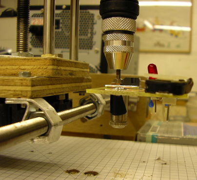
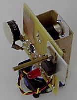
In case you're wondering about the long threaded bar holding the voltage regulator to the heat sink and circuit board, its purpose is to fit into the chuck of the drill mounted on my drilling machine - saving me the job of unbolting it.
When mounted, it'll look something like this:
When cutting dark paper, the width of the track looks to be about 0.25 mm. That's with me holding the paper so it might be less when mounted on something less shaky. Some of the surface mount chips I want to solder are very fine so I hope that's good enough. I won't know until I finish the heatsinking and power harness and source some suitable dark paper for a proper routing test.
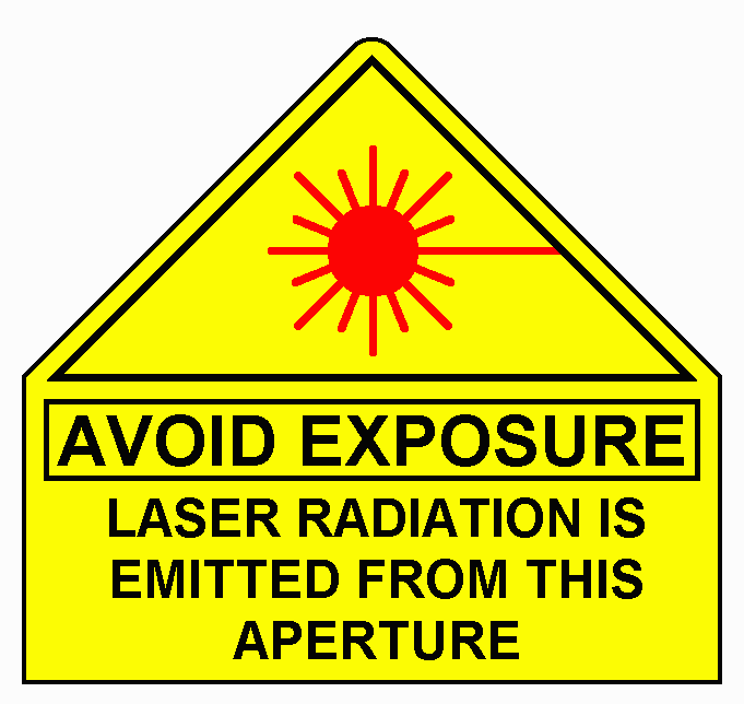
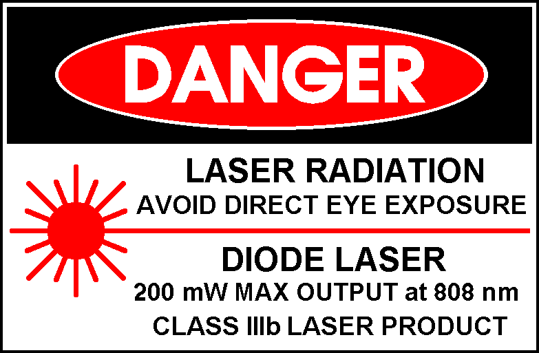
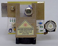
I've also got a couple of new warning signs to attach to the cutting head and drilling machine:
On the safety front, the cutting head is actually somewhat safer than a regular collimated beam. A collimated beam is fine and stays fine over long distances. The cutting head beam is focused to a point and then rapidly diverges so the power density is quickly reduced.
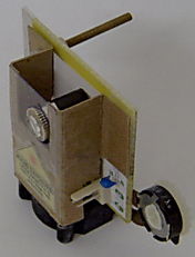
I have now fitted the fan and baffle to the cutting head:
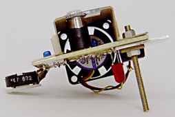
The fan is positioned so that one half of it cools the laser controller chip and the other cools the laser without blowing over the beam target.
The test results will have to wait until I've finished upgrading my drilling machine.
The laser stenciler board layout in Eagle format.
The ADL-80Y01TL 200 mW 808 nm laser diode at Farnell.
The iC-WKN laser diode controller at Farnell.
The acrylic collimating lenses at Thorlabs.
I built the circuit with a variable resistor so I could control the output power and it turns out that if you crank the power up, then you get a tiny pale red dot appearing. This made it easy to see that the beam was being focused about 2 cm from the outer lens.
Now despite all the power being focused onto a tiny spot, it can't cut white paper - but it can cut dark paper. Anything that strongly absorbs infra-red will heat up and cut. A brown-headed match will ignite rapidly but a pink-headed one won't. Take a pencil and shade in the pink head and it will ignite.
The other thing to note is that the laser controller chip gets hot when running at high outputs. The heatsink on the board isn't enough so I had to rig up a fan to keep it cool. If the laser controller chip gets too hot it automatically shuts itself down for safety.
I know it's de rigueur, so here for your viewing pleasure is the laser stenciler igniting a match. It's a bit tricky locating the focal point particularly from the angle I was doing it. You will notice that the flame goes out quite quickly too. That's because there's a big fan under the circuit board blowing air everywhere. Despite the cooling effects of the fan though, the match still goes up:
Laser stenciler igniting match.
I will need to fit a smaller fan to the side of the board so it can blow over the laser controller chip and over the metal laser tube but fit a baffle to stop it blowing over the beam target. It would be nice if the beam was a bit more powerful and I did leave some margin in the maximum output power setting. I think I'll wait and see before pushing it any harder. If a semiconductor laser gets too hot, it can slip into thermal runaway and burn itself out.
In case you're wondering about the long threaded bar holding the voltage regulator to the heat sink and circuit board, its purpose is to fit into the chuck of the drill mounted on my drilling machine - saving me the job of unbolting it.
When mounted, it'll look something like this:
When cutting dark paper, the width of the track looks to be about 0.25 mm. That's with me holding the paper so it might be less when mounted on something less shaky. Some of the surface mount chips I want to solder are very fine so I hope that's good enough. I won't know until I finish the heatsinking and power harness and source some suitable dark paper for a proper routing test.
I've also got a couple of new warning signs to attach to the cutting head and drilling machine:
On the safety front, the cutting head is actually somewhat safer than a regular collimated beam. A collimated beam is fine and stays fine over long distances. The cutting head beam is focused to a point and then rapidly diverges so the power density is quickly reduced.
I have now fitted the fan and baffle to the cutting head:
The fan is positioned so that one half of it cools the laser controller chip and the other cools the laser without blowing over the beam target.
The test results will have to wait until I've finished upgrading my drilling machine.
Resources
The laser stenciler schematic in Eagle format.The laser stenciler board layout in Eagle format.
The ADL-80Y01TL 200 mW 808 nm laser diode at Farnell.
The iC-WKN laser diode controller at Farnell.
The acrylic collimating lenses at Thorlabs.