
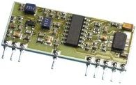
and here's the receiver:
There are no schematics at the moment because it was created with my old schematic capture software but the circuits are very simple. The only added wrinkle is that the transmitter and receiver modules require so little power that they are powered directly from a microcontroller I/O line which means they can be powered up or down as required thus saving more power.
My transmitter was designed to be on permanently but in sleep mode. It would periodically wake up, power up the transmitter module, send the unique ID code, power down the transmitter module and go back to sleep.
My receiver was a bit more complicated. It had a push button so that when held down, the microcontroller could power down the receiver module, enter sleep mode and stay that way until the button was pressed again. When active, it had to constantly analyse the data coming from the receiver module looking for the unique ID code. If it didn't receive the code within a certain time span, it would trigger an alarm to alert the owner that the laptop was out of range. Pressing the button would reset the alarm. I threw in an LED to provide some visual feedback of which mode the receiver was in.
So I built a prototype on breadboard and got both units into a working state. Then I tried my hand at building the next level of prototype - the scale working model.
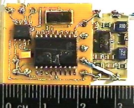
Here's the transmitter:
There are no schematics at the moment because it was created with my old schematic capture software but the circuits are very simple. The only added wrinkle is that the transmitter and receiver modules require so little power that they are powered directly from a microcontroller I/O line which means they can be powered up or down as required thus saving more power.
My transmitter was designed to be on permanently but in sleep mode. It would periodically wake up, power up the transmitter module, send the unique ID code, power down the transmitter module and go back to sleep.
My receiver was a bit more complicated. It had a push button so that when held down, the microcontroller could power down the receiver module, enter sleep mode and stay that way until the button was pressed again. When active, it had to constantly analyse the data coming from the receiver module looking for the unique ID code. If it didn't receive the code within a certain time span, it would trigger an alarm to alert the owner that the laptop was out of range. Pressing the button would reset the alarm. I threw in an LED to provide some visual feedback of which mode the receiver was in.
So I built a prototype on breadboard and got both units into a working state. Then I tried my hand at building the next level of prototype - the scale working model.
Here's the transmitter:
You can see the PIC microcontroller with ceramic
resonator, the voltage regulator with capacitor and the transmitter
module glued to the side of my printed circuit board. You can see
how small the board is. There is an even smaller version of this
microcontroller available but I wasn't sure at the time that I'd
be able to solder it onto the board. A production unit could
probably use a simpler, smaller microcontroller and possibly use an
internal oscillator rather than the external ceramic resonator and
would probably use a double-sided printed circuit board to minimise the
board area. Note that I soldered the microcontroller onto the
board before it was programmed and then programmed it in situ which
explains the presence of the three solder pads in the lower left of the
picture. Incidentally, this board has been sprayed with a thick
coat of lacquer. A production unit would probably be encased in
an epoxy resin coating.
Here's the receiver:
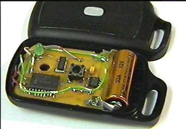
Here's the receiver:
Yes, I managed to squeeze the receiver into a
regular car remote key fob. The receiver module is hidden,
sitting underneath my printed circuit board. You can see the PIC
microcontroller with ceramic resonator, the voltage regulator with
capacitor, the LED and the push button all powered by a 12V lighter
battery. What you also can't see is a flat piezo-electric
transducer right at the bottom of the key fob. I programmed the
microcontroller to send a square wave to it so that it would act as the
alarm sounder. It wasn't very loud but it was something I already
had in stock.
The ceramic resonators for the PIC microcontrollers actually have three leads because they have capacitors built into them as well. They're a little more expensive than the regular ceramic resonators but they save on board space since you don't need additional capacitors.
The transmitter and receiver modules have a theoretical range of 70m. That's much further than I'd like my laptop to get away from me (incidentally I don't actually own a laptop!) before being notified, so the lack of room for a proper receiving aerial is actually an advantage in this case since it reduces the range.
Now I talked about keeping the power requirements low and I did do some measurements of the breadboard transmitter and receiver prototypes in action.
First up, the receiver with a supply voltage of 9V using a 7805 regulator:
Scanning for ID code 9.5mA
Alarm beeping 10mA
LED on 25mA
Sleeping 5.5mA
Now the receiver with a supply voltage of 5V without the regulator:
Scanning for ID code 3.5mA
Alarm beeping 4mA
LED on 18mA
Sleeping Too low to measure
Now the transmitter with a supply voltage of 9V using a 7805 regulator:
Sending ID code 7mA
Sleeping 4mA
Now the transmitter with a supply voltage of 5V without the regulator:
Sending ID code 2.5mA
Sleeping Too low to measure
The 12V lighter battery in the key fob prototype was rated at 33mAh @ 20kOhms for 66h to 6V. So for a receiver scanning at a current of somewhere between 3.5mA and 9.5mA, you would probably get a pretty good battery life. It would be nice to investigate a rechargeable option but that would probably need a larger case more along the lines of a pager clipped to your waistband.
Yes, this project did work but I failed to interest my company in developing it further. I suggested to them that this system could be used to monitor laptops that didn't leave the factory too by hooking a computer up to a receiver module (with a proper aerial) and keeping a track of all the unique ID codes coming in. If one is transmitting and then vanishes then it may be leaving the premises!
Alas, I failed to get either idea developed any further.
I like to think I was a little ahead of my time with project. A couple of years after I designed this project, a new PIC microcontroller was released with a built-in radio transmitter module! This was well before RFID was readily available too. These days, if you look around, you can get a Bluetooth version of this project idea. Bluetooth being ideal since it was only ever designed for short range use.
One day I'm going to go back and revisit the code to improve it with the knowledge and experience I have acquired since so I'm not going to share my current code at this time. Maybe this project will inspire you to come up with something similar but different.
<Back>