Optical S/PDIF Decoder
Here's a project I did for
Aaron. The Playstation 2 has an optical S/PDIF output (also known
as TOSLINK) and he wanted a device to decode the digital signal and
turn it into a analogue stereo audio one. S/PDIF is quite a
common signal now but it is usually found in electrical form on
computers and DVD players. It's quite an interesting signal too
in that it can be PCM audio like a CD/DAT player or contain raw data in
an MPEG or Dolby Digital format. The signals are all transmitted
using Manchester
coding whether they're electrical or optical. The advantage
of an optical system is, of course, that the fibre optic cable is
essentially impervious to electrical interference. Now I don't
like to build any circuit that I can't test so I was in luck because my
Panasonic DVD-RAM recorder does have an optical S/PDIF output.
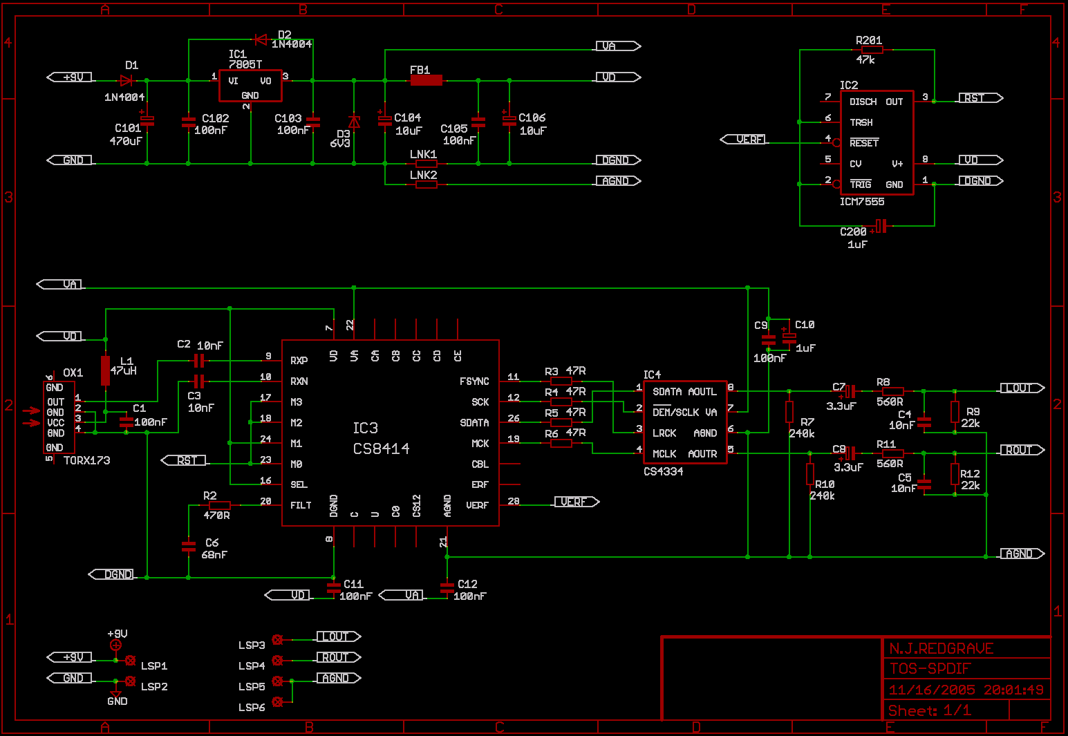
I looked around the 'net and found a circuit for a "coaxial" S/PDIF decoder. I grabbed the data sheets for the two main chips (the first being the decoder chip and the second being the DAC) to see if this could do the job. The decoder chip didn't care whether the data was the domestic S/PDIF or the commercial AES/EBU and the data sheet showed how to interface any of the possible signal types including TTL which is what a TOSLINK receiver produces.
So I reworked the interface to the circuit to use the TORX173 TOSLINK receiver.
I layed out a PCB and was
ready to purchase the components. That turned out to be
tricky. I found I could buy all the components except for the two
main chips. That's almost true - Farnell would sell me the chips
but they would have to be sent direct from their American arm at
enormous cost. The chips themselves weren't actually expensive so
in the end I got Aaron himself to buy the chips and send them to me.
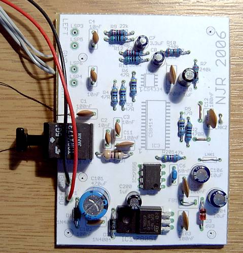
Ready at last, I manufactured a PCB and drilled it using my Drillcon100 drilling machine and fitted the components.
Ready at last, I manufactured a PCB and drilled it using my Drillcon100 drilling machine and fitted the components.
I plugged it into my DVD-RAM
player and powered it up. Did it work? Did it heck! I
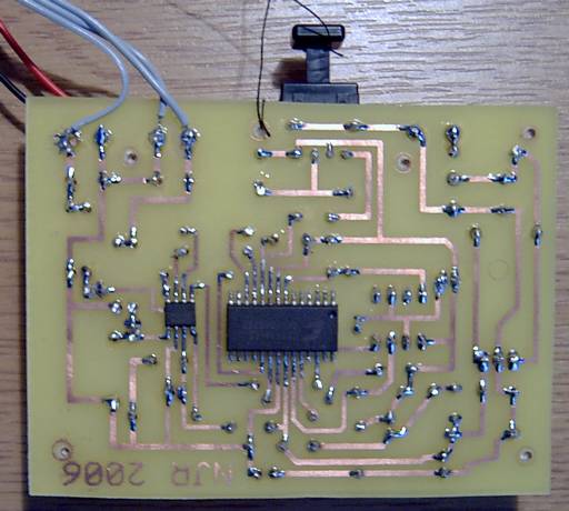
spent the next couple of days checking all the signals with my
oscilloscope in conjunction with the data sheets. I finally found
the problem and I should have guessed. Not all the pins on the
decoder chip are actually required for this circuit but one that
definitely was had a dry joint. I remelted the solder on that pin
and gave it a go. It burst into life immediately and the output
sounded very clean and noise-free.
I lacquered the board and sent it off to Aaron complete with a short fibre optic cable.
I should add that Aaron actually sent me two sets of chips so I still have enough to make another board. I haven't done so yet and I'm not sure if I'd build another TOSLINK-style one anyway. The DAC used in this circuit only decodes PCM audio but if swapped for a different one, it would be possible to decode raw streams with MPEG or Dolby Digital data. It might be nice to decode some of the additional data lines on the decoder chip for use on an informational display. We'll see.
<Back>